Download zip archive
Key Ideas
- Interrupt event handling
- Mechanical switch debouncing.
Description
This app note shows you how to interface an on-off switch to the eMote .NOW. When the switch is on (contacts are closed), it displays ON in the LCD display. When it is off (contacts are open), it displays OFF.
Compatibility
eMote.NOW 1.0, eMote version 4.3.0.14, Micro Framework SDK 4.3.2 and Visual Studio 2012 or 2013.
Complexity Level
Fairly introductory. There is some complexity with respect to key debouncing.
Setup
In this app note we will interface an on-off (single pole, single throw) switch. You will need:
- An eMote .NOW.
- A micro-USB cable to connect to the PC.
- A single pole, single throw switch (SPST). It can be a switch with separate On and Off positions, or it can be a push-button switch. You can also use a multi pole or multi throw switch, but we will only be using it as single pole, single throw. In the discussion we assume SPST.
- Hook up wire to connect the switch to the eMote .NOW.
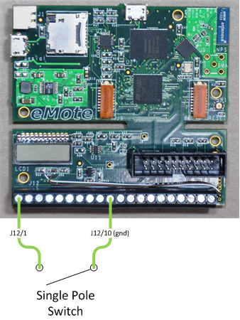
Now follow these directions (see the diagram):
-
Take two short lengths of wire, strip the ends, and attach a wire to each of the two terminals on the switch. If your switch has solder terminals, you'll need to solder the wire.
-
Connect one of the wires to connector J12/1 (that is, pin 1 of connector J12) and the other to J12/10. J12/1 is a general purpose I/O pin that we'll be using for input. J12/10 is ground.
-
Connect the USB cable to the eMote .NOW and to your PC. See the FAQ for general set-up and usage.
Getting Started
First, open the app note in Visual Studio. Check the properties of the project. The device shown should match the port assigned to your eMote .NOW. Press F5 to begin a debugging session.
If all goes well, the program will be deployed to the board and begin executing. When it has started, you can turn your switch on and off. Each time you do so, you will see the LCD show the switch status and the debug output panel in Visual Studio will show what's happening.
If you have a different version of the eMote firmware installed on your mote, you'll need to (a) delete the eMote references in the project and (b) add references to the correct version of the eMote DLLs.
Discussion
You will see comments in the code that document each part. Overall, here's what happens.
- Method Main gets things started. It sets up the LCD and sets up J11/1 as an InputPort with an interrupt handler. When it finishes, it goes into an infinite spin loop. Everything else that happens is triggered by an interrupt event.
- The field inputSwitch specifies J12/1 with pull-up resistor mode and interrupts on both leading and trailing edges and calls the interrupt handler inputSwitch_OnInterrupt when an interrupt occurs.
- Why resistor mode of pull-up? If an input pin has nothing connected to it, the state of the pin is undefined: it can be high, low or somewhere in between, and can vary at any time. To avoid this, the pull-up resistor mode guarantees that when the switch is open (so effectively nothing is connected), then it's state will be forced to high (hence the term pull-up). When the switch is closed, it is forced to ground and assumes a low value. If you'd like to learn more, see http://en.wikipedia.org/wiki/Pull-up_resistor.
- Why both interrupt edges? As the input changes from low (ground) to high we call that the leading . As it changes back to low, we call that the trailing edge. Edge interrupts detect changes, not absolute values. For this appnote, we want to cause an interrupt on both low and high edges. For more information, see http://en.wikipedia.org/wiki/Interrupt#Edge-triggered.
- Debouncing is handled by the class DebouncedSwitch in the Utility project. Switch bounce is normal and occurs with mechanical switches when the contacts make and break connection quickly while opening and closing. The result will be lots of interrupts all in a row, alternating leading and trailing edge. To avoid this, we introduce a one-shot timer (default 50 ms) that is set (or reset) for each interrupt. Thus the timer expires after we've waited a while after the last interropt. When it expires, the timer callback samples the GPIO input and returns that value. In addition, it's possible to press and release the switch so fast the the following happen:
- The trigger for switch-press (trailing edge) initiates the debounce timer.
- The switch is released before the timer expires. Hence the leading edge trigger is considered to be bounce and is ignored.
- The timer expires, reads the GPIO and returns a high value (switch is open).
In this case, the timer can return the same value twice in a row. To avoid this, it ensures that each value returned to the calling program is different than the last.
Suggestions
Suppose it's important to know in a positive sense whether the switch is on or off. As set up here, we can't distinguish between off and disconnected (say, a wire has come loose). Try adding a double-throw switch. Connect the common terminal to ground (J12/10) and the other terminals to J12/1 and /2, respectively. Change the program to detect and display three states, On, Off and Disconnected. Depending on the switch you choose, it might take a little while to move between On and Off, and you could get a false positive detection of Disconnected. Try changing the code to avoid this.